No products in the cart.
Tutorial of Using NRF24L01+ & Arduino Leave a comment
This is a simple short and easy tutorial for NRF24L01 Radio 2.4GHz Transmitter Receiver. In this tutorial I am going to control led using a pair of NRF24L01 transceiver.
Step 1: Small Introduction About NRF 24L01 transceiver
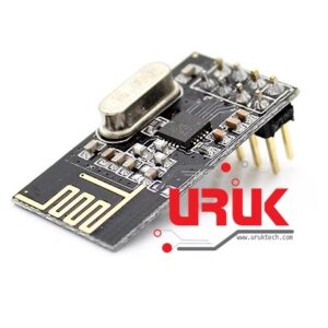
The nRF24L01 is a highly integrated, ultra low power (ULP) 2Mbps RF transceiver IC for the 2.4GHz ISM (Industrial, Scientific and Medical) band. With peak RX/TX currents lower than 14mA, a sub μA power down mode, advanced power management, and a 1.9 to 3.6V supply range, the nRF24L01 provides a true ULP solution enabling months to years of battery lifetime when running on coin cells or AA/AAA batteries.
Step 2: Material Require
– 2 PCS NRF24L01+2.4 GHz Wireless Transceiver module
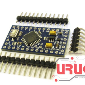
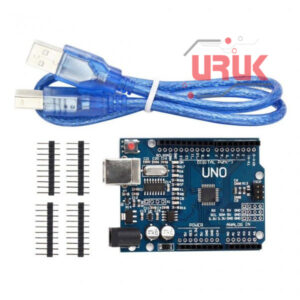
– 2 Arduino any (I have used one arduino R3 & nano)
– Male to. femal jumpers
– LED
– Any Switch
– 10K resistor
Step 3: Connections
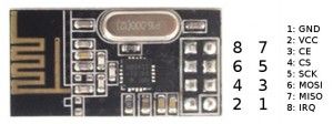
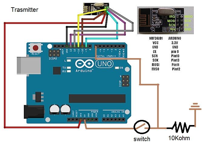
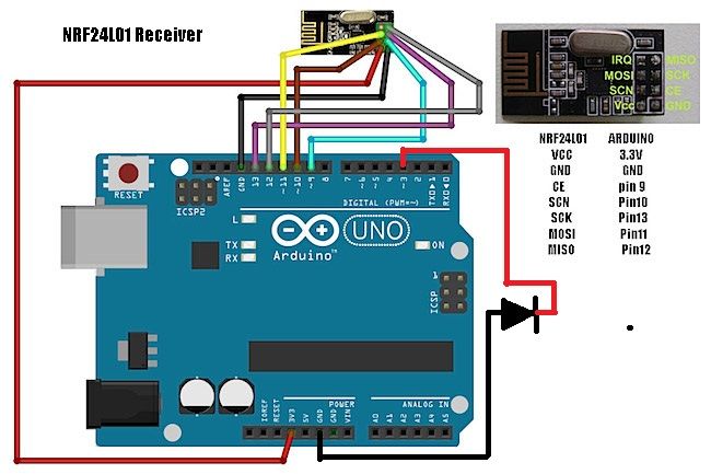
- Connect the following pins to your Arduino:as shown in figure
- Pin 9 – CE
- Pin 10 – CS(N)
- Pin 11 – MOSI
- Pin 12 – MISO
- Pin 13 – SCK
- 3.3v – VCC
- GND – GND
- On the Receiver Pin 3 – LED
- On the Transmitter Pin 7 – Button
- same connection for receiver and transmitter and you can use any arduino board
Step 4: Coding arduino
For coding arduino first we need some library files so follow the steps given below :
1. Download the ZIP file (library file zip folder from attachments ). Library Files
3. Unpack the ZIP file.
4. Go to arduino library folder
5. And paste both the folders named ” nFR24L01″ and “RF24” into it.
Now, program the Arduino receiver and transmitter
Code for Receiver
<p>#include <SPI.h><br>#include "nRF24L01.h"
#include "RF24.h"
int msg[1];
RF24 radio(9,10);
const uint64_t pipe = 0xE8E8F0F0E1LL;
int LED1 = 3;</p><p>void setup(void){
 Serial.begin(9600);
 radio.begin();
 radio.openReadingPipe(1,pipe);
 radio.startListening();
 pinMode(LED1, OUTPUT);}</p><p>void loop(void){
 if (radio.available()){
   bool done = false;
   while (!done){
     done = radio.read(msg, 1);
     Serial.println(msg[0]);
     if (msg[0] == 111){delay(10);digitalWrite(LED1, HIGH);}
     else {digitalWrite(LED1, LOW);}
     delay(10);}}
 else{Serial.println("No radio available");}}</p>
Code for Transmitter
<p>#include  <SPI.h><br>#include "nRF24L01.h"
#include "RF24.h"
int msg[1];
RF24 radio(9,10);
const uint64_t pipe = 0xE8E8F0F0E1LL;
int SW1 = 7;</p><p>void setup(void){
 Serial.begin(9600);
 radio.begin();
 radio.openWritingPipe(pipe);}</p><p>void loop(void){
 if (digitalRead(SW1) == HIGH){
 msg[0] = 111;
 radio.write(msg, 1);}}</p>
The items used in this experiment
المواد المستخدمة في التجربة يمكنكم اضافتها الى سلة مشترياتكم مباشرة من هنا
This is a last step after completing the circuit and coding part we can easily test it by switching “ON” and “OFF”.
When switch is “ON” on transmitter side connected to pin 7 of arduino then led glows on receivers side connected to pin 3 of arduino .Video Shows the output of this project.