Subtotal: 5,250 د.ع
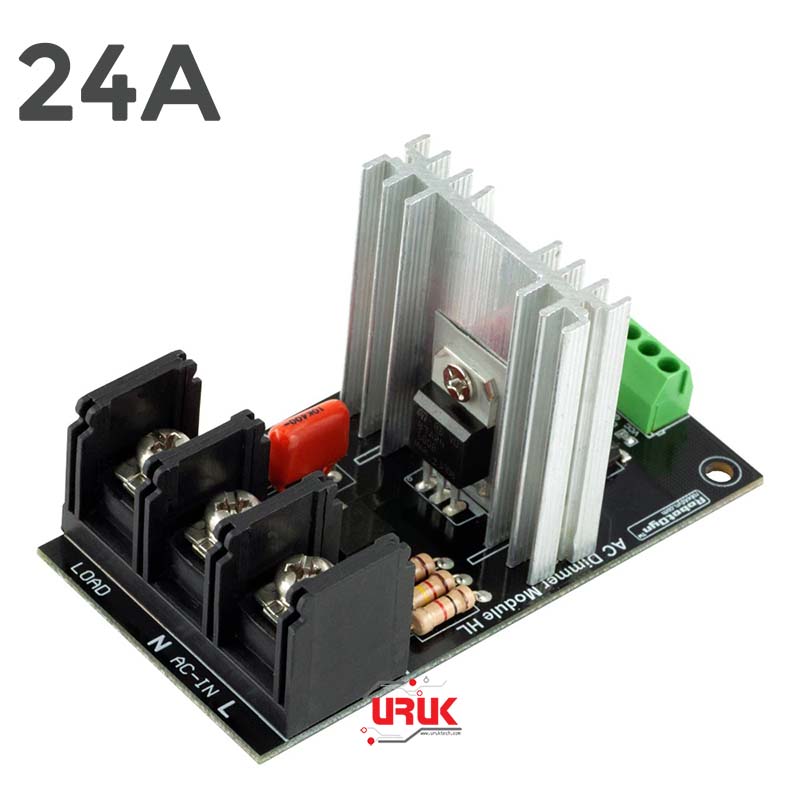
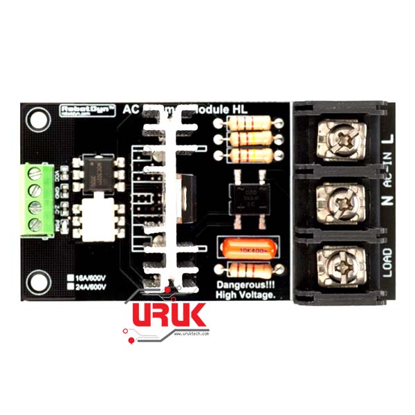
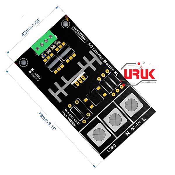
24A 600V AC Dimmer Module, 1 Channel, 3.3V/5V logic Control
In stock
مودل ديمر Dimmer للتحكم بقدرة تشغيل احمال AC بفولتية تصل لغاية 600 فولت وبتيار قدره 24 امبير. يمكن استخدام المودل للتحكم بتشغيل الاحمال كالإنارة والمحركات عبر المايكروكونترولر مثل الاردوينو او ESP لمشاريع التحكم وانترنت الأشياء او مشاريع البيوت الذكية والسيطرة التلقائية. يحتوي المودل على عدة ميز، أهمها انه يمكن التحكم به عبر أي متحكم بإشارة تحكم بفولتية 3.3 او 5 فولت واحتوائه على الدوائر اللازمة لتحسس إشارة الـ Zero Cross لغرض التحكم بشكل دقيق. المكتبات الخاصة باستخدامه وكافة الملفات الخاصة به متوفرة على صفحة المنتج في تطبيق وموقع اوروكتيك.
25,750 د.ع
In stock
24A 600V AC Dimmer Module, 1 Channel, 3.3V/5V logic Control
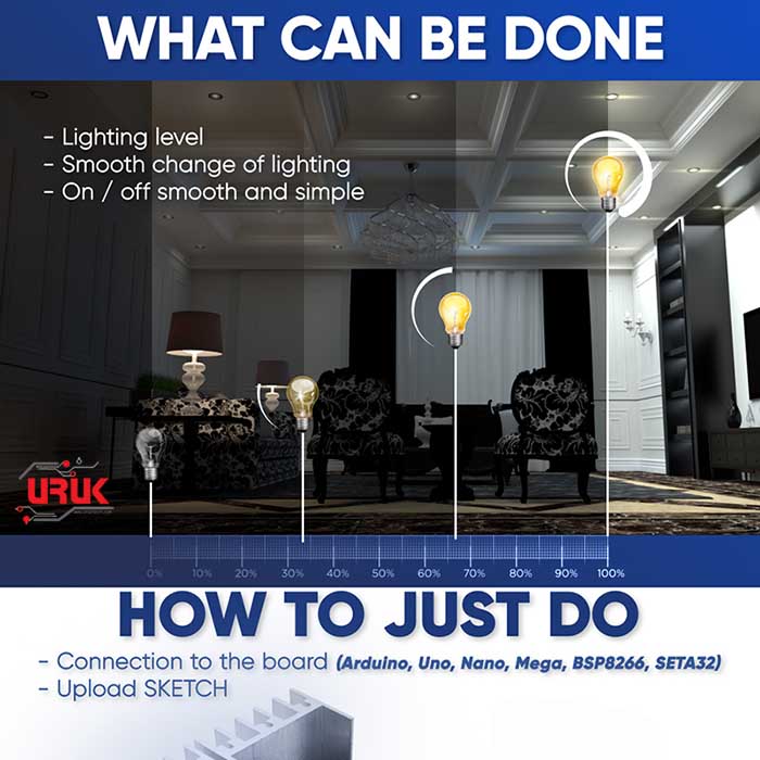
The AC Dimmer is designed to control the alternating current voltage, which can transfer current up to 600V 24A. In most cases, Dimmer is used to turning power ON/OFF for lamps or heating elements, it can also be used in fans, pumps, air cleaners, etc. Lately, Dimmer has become an often used decision for the smart home systems. For example, when you need to smoothly change the voltage power. The power is slowly turning ON or OFF.
Power part of dimmer is isolated from the control part, to exclude the possibility of high current disruption to a microcontroller. The logical level is tolerant to 5V and 3.3V, therefore it can be connected to the microcontroller with 5V and 3.3V level logic.
In Arduino, the dimmer is controlled with RBDdimmer.h library, which uses external interrupts and process time interrupts. It simplifies the code writing and gives more processing time for main code. Which is why you can control multiple Dimmers from one microcontroller.
You can download RBDDimmer.h library and a few examples in «Documents» or on GitHub. We are constantly updating our library, so we recommend checking for the website updates or subscribe to our newsletter.
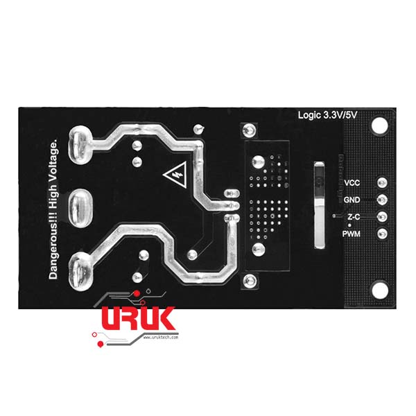
Dimmer is connected to Arduino controllers via two digital pins. First (Zero) to control the passing of Phase Null of AC, which is used to initiate the interrupt signal. Second (DIM/PSM) to control (dim) current.
Note that Zero requires connection to designated microcontroller pins (which are different depending on the model of Uno, Nano, Leonardo, Mega), since it tied to microcontroller interrupts.
Specification
Controlled Voltage: up to 600V
TRIAC: BTA24—600V
Current: 24A Max.
Isolation: Optocoupler
Logic level: 3.3V/5V
Zero point: Logic level
Modulation (DIM/PWM): logic level ON/OFF TRIAC
Signal current: >10mA
Operating temperatures: −20°C to 80°C
Theory:
Dimming can be achieved by Pulse Skip Modulation:
• Method 1 — One or more cycles (sine wave signal) are transferred to the load while following one or several cycles are blocked.
• Method 2 — Partial transference of each sine wave to the load.
• Method 3 — Generation of modulated full sine signal of different frequency up to few hundred Hertz. This method requires specialized powerful AC generators with different modulation.
Methods 1 and 2 are the easiest to execute with the help of a Dimmer and program code: in both cases, there is a need of circuit that detects the zero crossing and can control a TRIAC.
Documentation & Download
Documents (Instruction manuals, schematics, etc), links:
https://robotdyn.com/Mod-Dimmer-5A-1L-EN
Library and sketch examples:
• Dimmer Library (RBDdimmer.h): https://github.com/RobotDynOfficial/RBDDimmer
• Discussion and support on FB: https://www.facebook.com/342167936199454/posts/623343184748593/
• Video channel: https://www.youtube.com/channel/UCh3PdwD_x7tg5sUUt3EfpfQ/videos
Package Includes:
1 x AC Dimmer 24A
- Controlled Voltage: up to 600V
- TRIAC: BTA16—600V / BTA24—600V
- Isolation: Optocoupler
- Logic level: 3.3V/5V
- Zero point: Logic level
- Modulation (DIM/PWM): logic level ON/OFF TRIAC
- Signal current: >10mA
- Operating temperatures: −20°C to 80°C
Based on 0 reviews
Only logged in customers who have purchased this product may leave a review.







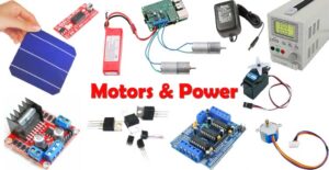

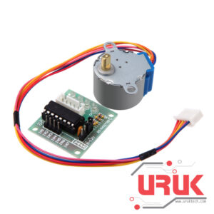 Stepper Motor + Driver Board
 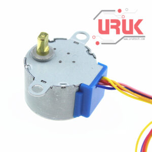 4-phase Stepper Motor
 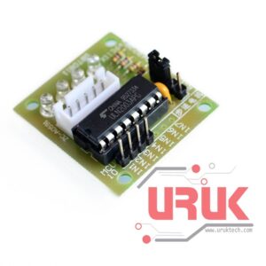 ULN2003 Driver Board






There are no reviews yet.