Step 3: ESP-01 Setup continued
Upload the BareMinimum example to ensure that no previous programs are running and using the serial communication channel. Next, open the serial monitor and type the following command:
AT
You should get an “OK” response. This means that the module is working and that you are good to go. Now we are ready to test a two way communication between the module and another device.
Step 4: Basic AT Commands
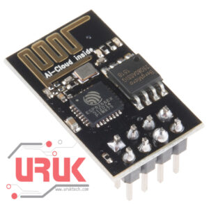
The ESP8266 ESP-01 module has three operation modes:
- Access Point (AP)
- Station (STA)
- Both
In AP the Wi-Fi module acts as a Wi-Fi network, or access point (hence the name), allowing other devices to connect to it. This does not mean that you will be able to check your Facebook from your device while the ESP-01 module is operating in the AP mode. It simply establishes a two way communication between the ESP8266 and the device that is connected to it via Wi-Fi.
In STA mode, the ESP-01 can connect to an AP such as the Wi-Fi network from your house. This allows any device connected to that network to communicate with the module.
The third mode of operation permits the module to act as both an AP and a STA.
Step 5: Basic AT Commands – STA Mode
In this tutorial, we are going to set the module to operate in STA mode by typing the following command:
AT+CWMODE=1
The corresponding number for each mode of operation is as follows:
Step 6: Basic AT Commands – Check Mode
If you want to check what mode your Wi-Fi module is in, you can simply type the following command:
AT+CWMODE?
This will display a number (1, 2, or 3) associated with the corresponding mode of operation.
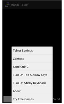
Step 7: Basic AT Commands – Connecting Wi-Fi Network
Once we have the ESP-01 operating in STA mode, we need to connect to a Wi-Fi network. First we can check if we are already connected to one by sending the command:
AT+CIFSR
This will display the station IP address of our ESP-01 module. If you don’t get an IP address after entering the previous command, use the following command to connect to your network:
AT+CWJAP= “Wi-FiNetwork”,“Password”
Type the name of your Wi-Fi network and the password to connect to it. Make sure you include the quotation marks. After a couple of seconds, you should get an “OK” response. You can check again to see if you have an IP address using the AT+CIFSR command.
Step 8: Basic AT Commands – Enable Connections
Then we need to enable multiple connections before we can configure the ESP8266 ESP-01 module as a server. Type the next command:
AT+CIPMUX=1
Once again, each number is associated with a type of connection:
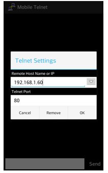
The following step is to start the server at port 80:
AT+CIPSERVER=1,80
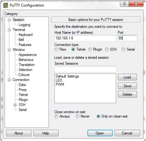
The first number is used to indicate whether we want to close server mode (0), or open server mode (1). The second number indicates the port that the client uses to connect to a server. We chose port 80 because this is the default port for HTTP protocol.
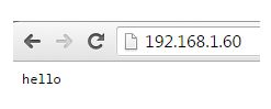
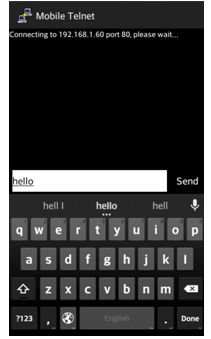
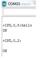
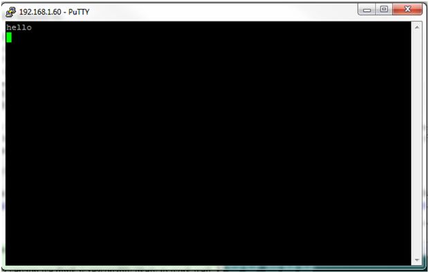
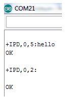
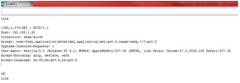
Step 9: Basic At Commands – Response


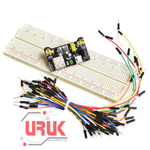 Prototyping Kit
1 × 7,500 د.ع
Prototyping Kit
1 × 7,500 د.ع 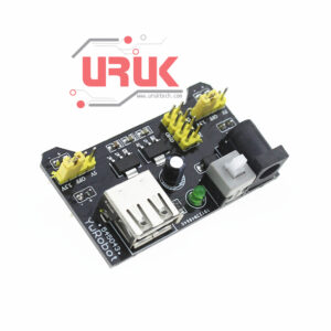 Breadboard Power Module MB102
1 ×
Breadboard Power Module MB102
1 ×  Prototype Breadboard
1 ×
Prototype Breadboard
1 × 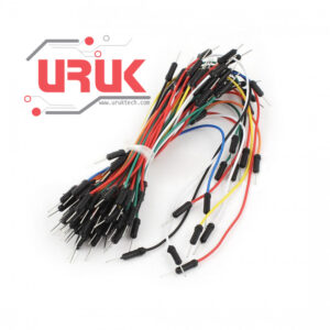 65 Flexible Wire Jumpers
1 ×
65 Flexible Wire Jumpers
1 ×