// include the library code:
#include <LiquidCrystal.h>
#include <SD.h>
#include <Wire.h>
#include “RTClib.h”
const int chipSelect = 10;
//File dataFile;
File logfile;
// initialize the library with the numbers of the interface pins
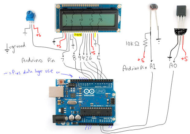
LiquidCrystal lcd(7, 8, 9, 4, 2, 6);
//TMP36 Pin Variables
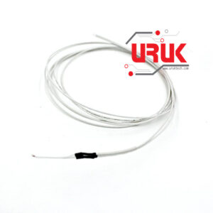
int temperaturePin = 0; //the analog pin the TMP36’s Vout (sense) pin is connected to the resolution is 10 mV / degree centigrade(500 mV offset) to make negative temperatures an option
//PhotoResistor Pin
int lightPin = 1; //the analog pin the photoresistor is connected to the photoresistor is not calibrated to any units so this is simply a raw sensor value (relative light)
//led for light sensor
int lcdRed = 3; //the pin the LED is connected to
int lcdBlue = 5; //the pin the LED is connected to
RTC_DS1307 RTC; // define the Real Time Clock object
//========================================================
void setup() {
// set up the LCD’s number of columns and rows:
lcd.begin(16,2);
Serial.begin(9600); //Start the serial connection with the copmuter
//to view the result open the serial monitor
//last button beneath the file bar (looks like a box with an antena
pinMode(lcdRed, INPUT); //sets the led pin to input
pinMode(lcdBlue, INPUT); //sets the led pin to input
Wire.begin();
RTC.begin();
//—————————————-
if (! RTC.isrunning()) {
Serial.println(“RTC is NOT running!”);
// following line sets the RTC to the date & time this sketch was compiled
RTC.adjust(DateTime(__DATE__, __TIME__));
}
//——————————-
Serial.print(“Initializing SD card…”);
// make sure that the default chip select pin is set to
// output, even if you don’t use it:
pinMode(SS, OUTPUT);
// see if the card is present and can be initialized:
if (!SD.begin(chipSelect)) {
Serial.println(“Card failed, or not present”);
// don’t do anything more:
while (1) ;
}
Serial.println(“card initialized.”);
// Open up the file we’re going to log to!
// dataFile = SD.open(“datalog.txt”, FILE_WRITE);
// if (! dataFile) {
// Serial.println(“error opening datalog.txt”);
// Wait forever since we cant write data
// while (1) ;
// }
//—————–
// create a new file
char filename[] = “LOGGER00.CSV”;
for (uint8_t i = 0; i < 100; i++) {
filename[6] = i/10 + ‘0’;
filename[7] = i%10 + ‘0’;
if (! SD.exists(filename)) {
// only open a new file if it doesn’t exist
logfile = SD.open(filename, FILE_WRITE);
break; // leave the loop!
}
}
Serial.print(“Logging to: “);
Serial.println(filename);
logfile.println(“,,,Willy,Reen”);
logfile.println(“Data Logging File”);
logfile.println(“Date,Temp(F),Light”);
}
//=========================================================
void loop() {
float temperature = getVoltage(temperaturePin); //getting the voltage reading from the temperature sensor
temperature = ((temperature – .5) * 100)*1.8+32; //converting from 10 mv per degree wit 500 mV offset
//to degrees ((volatge – 500mV) times 100)
// Serial.println(temperature); //printing the result
// delay(500); //waiting a second
//————————
int lightLevel = analogRead(lightPin); //Read the
lightLevel = map(lightLevel, 0, 900, 0, 150); //adjust the value 0 to 900 to span 0 to 255
lightLevel = constrain(lightLevel, 0, 150); //make sure the value is betwween 0 and 255
//////
int tempLevel = analogRead(temperaturePin)*100; //Read the
tempLevel = map(tempLevel, 66, 82, 0, 150); //adjust the value 0 to 900 to span 0 to 255
tempLevel = constrain(tempLevel, 0, 150); //make sure the value is betwween 0 and 255
analogWrite(lcdBlue, lightLevel); //write the value
analogWrite(lcdRed, tempLevel); //write the value
//———————————————————-
String dataString = “”;
//date time stuff——————————————-
//——————————————————-
//logfile.println(“”);
DateTime now = RTC.now();
// log time
// logfile.print(now.unixtime()); // seconds since 1/1/1970
// logfile.print(“, “);
logfile.print(‘”‘);
logfile.print(now.year(), DEC);
logfile.print(“/”);
logfile.print(now.month(), DEC);
logfile.print(“/”);
logfile.print(now.day(), DEC);
logfile.print(” “);
logfile.print(now.hour(), DEC);
logfile.print(“:”);
logfile.print(now.minute(), DEC);
logfile.print(“:”);
logfile.print(now.second(), DEC);
logfile.print(‘”‘);
logfile.print(“,”);
//
logfile.print(temperature);
logfile.print(“,”);
logfile.print(lightLevel);
delay(500);
//—————-
/*
// read sensors and append to the string:
for (int analogPin = 0; analogPin < 2; analogPin++) {
int sensor = analogRead(analogPin);
dataString += String(sensor);
if (analogPin < 1) {
dataString += “,”;
}
}
*/
// dataFile.println(dataString);
logfile.println(dataString);
// Serial.println(dataString);
// dataFile.flush();
logfile.flush();
//———————————————————–
// set the cursor to (0,0):
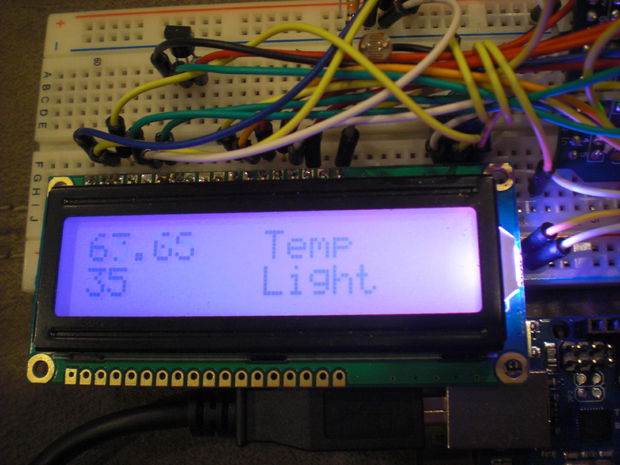
lcd.setCursor(0, 0);
// print from 0 to 9:
// for (int thisChar = 0; thisChar < 10; thisChar++) {
lcd.print(temperature);
// lcd.print(myString);
lcd.setCursor(0, 1);
lcd.print(lightLevel);
lcd.setCursor(8, 0);
lcd.print(“Temp”); //display temp on the lcd
lcd.setCursor(8, 1);
lcd.print(“Light”); //display light on the lcd
delay(500);
//———————lcd backlight
// lightLevel = constrain(lightLevel, 0, 255);//make sure the
//value is betwween
//0 and 255
}
//————————————————————
// set the cursor to (16,1):
// lcd.setCursor(16, 1);
// set the display to automatically scroll:
// lcd.autoscroll();
// print from 0 to 9:
// for (int thisChar = 0; thisChar < 10; thisChar++) {
// lcd.print(thisChar);
// delay(500);
// }
// turn off automatic scrolling
// lcd.noAutoscroll();
// clear screen for the next loop:
// lcd.clear();
//}
//==========================================================
float getVoltage(int pin){
return (analogRead(pin) * .004882814); //converting from a 0 to 1023 digital range
// to 0 to 5 volts (each 1 reading equals ~ 5 millivolts
}


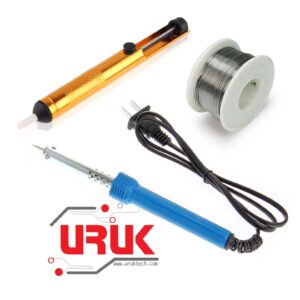 Soldering Kit
1 × 14,000 د.ع
Soldering Kit
1 × 14,000 د.ع 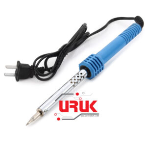 40 Watt Soldering Iron
1 ×
40 Watt Soldering Iron
1 × 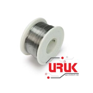 Solder Wire 50g 0.8mm
1 ×
Solder Wire 50g 0.8mm
1 ×  Desoldering Pump Sucker (Solder Remover Tool)
1 ×
Desoldering Pump Sucker (Solder Remover Tool)
1 ×  Standard DC Motor (R130)
1 × 750 د.ع
Standard DC Motor (R130)
1 × 750 د.ع 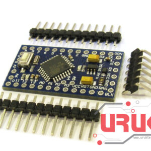 Arduino Pro Mini 5V/16MHz
1 × 9,000 د.ع
Arduino Pro Mini 5V/16MHz
1 × 9,000 د.ع  9V to Barrel Jack Adapter
1 × 1,000 د.ع
9V to Barrel Jack Adapter
1 × 1,000 د.ع 


Good post. I learn one thing more challenging on different blogs everyday. It’ll all the time be stimulating to read content from different writers and practice a bit something from their store. I抎 desire to make use of some with the content material on my weblog whether you don抰 mind. Natually I抣l offer you a hyperlink on your internet blog. Thanks for sharing.
good job dear