-
×
 RFID Proximity Keyfobs Ring 125KHz
1 × 500 د.ع
RFID Proximity Keyfobs Ring 125KHz
1 × 500 د.ع -
×
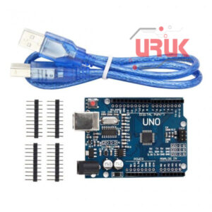 Arduino Uno SMD
1 × 10,250 د.ع
Arduino Uno SMD
1 × 10,250 د.ع
Subtotal: 10,750 د.ع
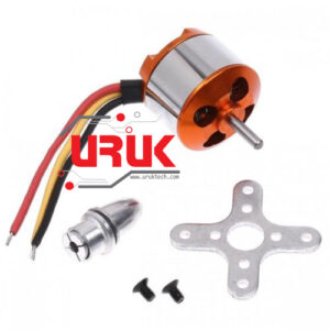
Electronic speed control (most commonly known as ESC) are nasty beasts: not from the controlling software point of view but for the way they need to be powered up, and because they need to be calibrated.
Especially the calibration is important because otherwise the ESC doesn’t know which are the limits of the transmitter, and it cannot control precisely the speed of the motor.
Before putting a ESC in any complex Arduino project, it is better to get used to how a ESC works using a very simple sketch.
But before seeing the code, let’s see how to wire it up, because care must be taken otherwise nothing will work.
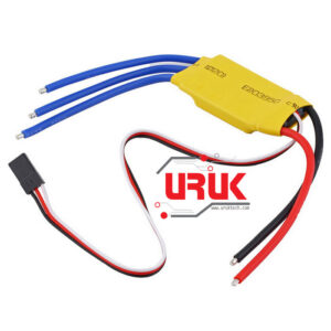
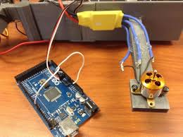
Wiring up the circuit and powering the ESC
Usually ESCs need a voltage higher than the one provided by the Arduino from his 5V pin: typically they need 2 LiPo cells (around 8V). To achieve that all the circuit must be powered from an external power supply connected directly to the ESC and not via the Arduino, which will be powered by the BEC circuit of the ESC. To make that happen it’s enough to connect the red and black of the control connector to the 5V and GDN of the Arduino board.
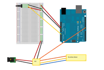
The rest of the circuit is pretty easy: from pin 9 of the Arduino we have the signal for the ESC, and into pin 0, the voltage reading from the potentiometer comes in.
Code Explanation
A ESC is made to receive inputs from a R/C transmitter, so it works as a servo: to control it you can use the Arduino Servo Library, so the test code is based on the servo library basic example published on the Arduino site.
It just takes the reading of the “throttle”, maps it from 0-1023 to 0-179 (analogue reading to servo “degrees”) and then sends it to the ESC via the Servo library. Even in its extreme simplicity this sketch it very useful when you want to calibrate a new ESC to work with the Servo library of Arduino.
Now that everything is setup, chances are that you motor might not rotate, or might rotate only forward, or might rotate only to 80% of the throttle (forward and reverse) and then stop: all these are symptoms of lack of calibration, or a calibration done with a different range of PWM signals.
More or less all ESCs have a similar calibration procedure:
Another possibility is that even after that procedure, the motor will not turn immediately in reverse, or will only go 50% of forward speed: that’s because ESCs are programmable, and you can change many of their behaviours via either a programming card or via, again as with the calibration, hearing and decoding beeps and blinks.
#include <Servo.h>
Servo esc;
int throttlePin = 0;
void setup()
{
esc.attach(9);
}
void loop()
{
int throttle = analogRead(throttlePin);
throttle = map(throttle, 0, 1023, 0, 179);
esc.write(throttle);
}
Select at least 2 products
to compare