-
×
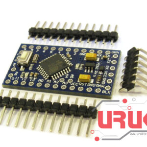 Arduino Pro Mini 5V/16MHz
1 × 9,000 د.ع
Arduino Pro Mini 5V/16MHz
1 × 9,000 د.ع
Subtotal: 9,000 د.ع
Line follower Robot is a machine which follows a line, either a black line or white line. Basically, there are two types of line follower robots: one is black line follower which follows black line and second is white line follower which follows white line. Line follower actually senses the line and run over it.
Concepts of Line Follower
Concept of working of line follower is related to light. We use here the behavior of light at black and white surface. When light fall on a white surface it is almost full reflected and in case of black surface light is completely absorbed. This behavior of light is used in building a line follower robot.
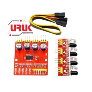
In this arduino based line follower robot we have used IR Transmitters and IR receivers also called photo diodes. They are used for sending and receiving light. IR transmits infrared lights. When infrared rays falls on white surface, it’s reflected back and catched by photodiodes which generates some voltage changes. When IR light falls on a black surface, light is absorb by the black surface and no rays are reflected back, thus photo diode does not receive any light or rays.
Here in this line follower robot when sensor senses white surface then arduino gets 1 as input and when senses black line arduino gets 0 as input.
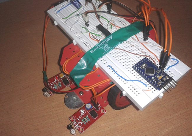
The whole line follower robot can be divided into 3 sections: sensor section, control section and driver section.
Sensor section:
This section contains IR diodes, potentiometer, Comparator (Op-Amp) and LED’s. Potentiometer is used for setting reference voltage at comparator’s one terminal and IR sensors are used to sense the line and provide a change in voltage at comparator’s second terminal. Then comparator compares both voltages and generates a digital signal at output. Here in this line follower circuit we have used two comparator for two sensors. LM 358 is used as comparator. LM358 has inbuilt two low noise Op-amps.
Control Section:
Arduino Pro Mini is used for controlling whole the process of line follower robot. The outputs of comparators are connected to digital pin number 2 and 3 of arduino. Arduino read these signals and send commands to driver circuit to drive line follower.
Driver section:
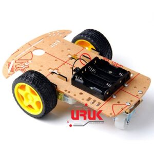
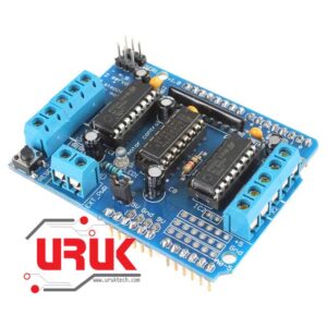
Driver section consists motor driver and two DC motors. Motor driver is used for driving motors because arduino does not supply enough voltage and current to motor. So we add a motor driver circuit to get enough voltage and current for motor. Arduino sends commands to this motor driver and then it drive motors.
Working of line follower is very interesting. Line follower robot senses black line by using sensor and then sends the signal to arduino. Then arduino drives the motor according to sensors’ output.
Here in this project we are using two IR sensor modules namely left sensor and right sensor. When both left and right sensor senses white then robot move forward.
If left sensor comes on black line then robot turn left side.
If right sensor sense black line then robot turn right side until both sensor comes at white surface. When white surface comes robot starts moving on forward again.
If both sensors comes on black line, robot stops.
Circuit Diagram
Complete circuit diagram for arduino based line follower robot is shown in the above iamge. As you can see output of comparators is directly connected to arduino digital pin number 2 and 3. And motor driver’s input pin 2, 7, 10 and 15 is connected to arduino’s digital pin number 4, 5, 6 and 7 respectively. And one motor is connected at output pin of motor driver 3 and 6 and another motor is connected at pin 11 and 14.
Program Explanation
In program, first of all we defined input and output pin, and then in loop we checks inputs and sends output according to inputs to output pin for driving motor. For checking input pin we used “if” statements.
There are four conditions in this line following robot that we read by using arduino. We have used two sensor namely left sensor and right sensor.
| Input | Output | Movement
Of Robot |
||||
| Left Sensor | Right Sensor | Left Motor
|
Right Motor | |||
| LS | RS | LM1 | LM2 | RM1 | RM2 | |
| 0 | 0 | 0 | 0 | 0 | 0 | Stop |
| 0 | 1 | 1 | 0 | 0 | 0 | Turn Right |
| 1 | 0 | 0 | 0 | 1 | 0 | Turn Left |
| 1 | 1 | 1 | 0 | 1 | 0 | Forward |
We write program according to the conditions shown in table above.
/*—— Program for Line Follower Robot using Arduino—– */
/*——-definning Inputs——*/
#define LS 2 // left sensor
#define RS 3 // right sensor
/*——-definning Outputs——*/
#define LM1 4 // left motor
#define LM2 5 // left motor
#define RM1 6 // right motor
#define RM2 7 // right motor
void setup()
{
pinMode(LS, INPUT);
pinMode(RS, INPUT);
pinMode(LM1, OUTPUT);
pinMode(LM2, OUTPUT);
pinMode(RM1, OUTPUT);
pinMode(RM2, OUTPUT);
}
void loop()
{
if(digitalRead(LS) && digitalRead(RS)) // Move Forward
{
digitalWrite(LM1, HIGH);
digitalWrite(LM2, LOW);
digitalWrite(RM1, HIGH);
digitalWrite(RM2, LOW);
}
if(!(digitalRead(LS)) && digitalRead(RS)) // Turn right
{
digitalWrite(LM1, LOW);
digitalWrite(LM2, LOW);
digitalWrite(RM1, HIGH);
digitalWrite(RM2, LOW);
}
if(digitalRead(LS) && !(digitalRead(RS))) // turn left
{
digitalWrite(LM1, HIGH);
digitalWrite(LM2, LOW);
digitalWrite(RM1, LOW);
digitalWrite(RM2, LOW);
}
if(!(digitalRead(LS)) && !(digitalRead(RS))) // stop
{
digitalWrite(LM1, LOW);
digitalWrite(LM2, LOW);
digitalWrite(RM1, LOW);
digitalWrite(RM2, LOW);
}
}
Select at least 2 products
to compare